CHENEAU BRACE
Dr. Chêneau, inspired by Abbot, fabricated the original Chêneau Brace in 1979. The Chêneau brace is commonly used for the treatment of scoliosis and thoracic hypokyphosis in many European countries such as Spain, France, and Germany as well as other countries like Israel and Russia. However, it is not commonly prescribed in North America and the UK. The brace is commonly known as el corse de Cheneau, Wood, G, Master by thesis, 2003.
The brace is fabricated in polypropylene and has an anterior opening with Velcro straps for fastening. The Chêneau brace is defined as a thermoplastic brace modelled on a hyper-corrected positive plaster mould of the patient. The general correction principle is that of detorsion and sagittal plane normalisation, which would correct the coronal and transversal planes, resulting in some elongation of the spine, without any significant distraction force, (Rigo, 1999a).
The objectives of the Chêneau brace are to obtain a three-dimensional correction of the scoliotic deformity, with emphasis not only on the coronal and transverse planes, but also on the sagittal plane (Matthiass and Heine, 1984; Syndikus et al., 1988; Giorgi et al., 1996; Losito et al., 1996; Kotwicki et al., 1999).
|
Patient in above Cheneau brace hand modified and delivered in Malaga Spain by Grant Wood, reference from Master by thesis on the Cheneau brace Grant I. Wood, 2003. |
The deformation of the scoliotic body consist of (Chêneau 1996a, 1996b):
1. Convexities-concavities.
2. Sagittal configuration deformity.
3. Rotation of the pelvis and shoulders
4. Lateral displacement.
1. The paired convexities and concavities: in an oblique plane the brace reduces the convexities and transfers tissues from the convex humps in the direction of the concave flat areas. All abnormal protrusions with respect to the normal physiological shape must be submitted to pressure.
2. Sagittal configuration deformity: often, abnormal thoracic kyphosis and lumbar lordosis is presented in the scoliotic patient.
3. Torsion of the pelvis and rotation of the shoulders: the brace must produce a detorsion of the pelvis and derotation of the shoulders.
4. The lateral displacement: in a transverse plane the brace establishes a balance of the shoulders and thorax over the sacrum.
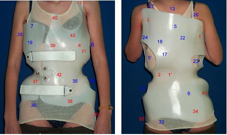
Chêneau (1990) provided a number system to indicate pressure and expansion zones on the Chêneau brace. This number system facilitates the identification of important zones on the Chêneau brace, plaster of Paris cast and the patient's body (figure 3.16a and b). The system lists number 1 through number 43, however some numbers are missing as the evolution of the brace has made them obsolete. The number system is used in all different types of classifications of scoliosis and curves, hence it is not limited to only one type of curve. However, not all the numbers in this number system are utilised in all cases. This is because sometimes a particular number may not be utilised as its corresponding function is not required.
Additionally, the location of the numbers often change from being on the right side of the brace to the left side and vice versa, as each scoliosis case is treated independently. As a result, the locations of these numbers are often determined by the direction of the curve convexity. Therefore the brace design is different for each individual case. The basic location of the pressure and expansion zones using the Chêneau brace number system and their corresponding functions are indicated below.
1: The location of the pressure zone 1 is on the convex side of the thoracic or thoracolumbar curve on the dorsal aspect of the brace. The function of this pressure is for the correction of the thoracic or thoracolumbar curve in the coronal plane and rotation of the vertebral column in the transverse plane.
1: The location of pressure zone 1´ is on the convex side of the lumbar curve on the dorsal aspect of the brace. This pressure zone is extended to the posterior midline in the case of lumbar hypolordosis, which is for the correction of the deformity in the sagittal plane.
2: The location of the pressure zone 2 is on the convex side of the lumbar curve on the dorsal aspect of the brace. The function of this pressure is for the correction the lumbar curve in the coronal plane and if present, correction of the lumbar hypolordosis deformity in the sagittal plane.
3: The pressure zone 3 applies a counterforce to the axilla that works on the opposite side to zone 1, which is for the correction of the thoracic and thoracolumbar curve in the coronal plane. Also, in the case of an unbalanced trunk over the pelvis, this force pushes the trunk to the midline of the body, placing it over the pelvis. When retropulsion of the shoulder is present, this force lifts the lower shoulder superiorly.
3': The location of pressure zone 3' is at the same level as 3´, but it is more posteriorly placed to move the retropulsion shoulder ventrally in the sagittal plane.
4: The location of pressure zone 4 is on the ventral aspect of the trunk. This force is placed adjacent to the pressure zone 1. The function of these forces is to work together to reduce the large diameter of the oval shaped thorax, which facilitates the derotation of the thoracic region in the transverse plane.
5: The location of expansion zone 5 is beside the thoracic and thoracolumbar curve and pressure zone 1. The function of this expansion zone is to provide a room or space for the expansion of the trunk, which allows respiratory movement, and permits small voluntary and involuntary movements as well as the patient’s growth. This provides an active mechanism of correction in the direction of derotation and rekyphosis,
5´: The location of this expansion zone is on the concave side of the thoracic curve and is opposite to pressure zone 1. The function of this expansion zone is to provide a room or space for the expansion of the trunk, which corrects the thoracic curve in the coronal plane.
6: The location of expansion zone 6 is on the posterior aspect of the hemipelvis that is in anteversion. This provides a space for the derotation the hemipelvis.
7: The location of expansion zone 7 is on the ventral aspect and is adjacent to pressure zone 3. The function is to provide a large space for the correction of the rotation and hypokyphosis of the thoracic region.
12: The location of pressure zone 12 is in the subclavicular region of the lower shoulder, which is positioned in retropulsion. The function is to facilitate control of the retropulsion shoulder in the sagittal plane.
13: The location of expansion zone 13 is outside the dorsal superior trimline of the brace above expansion zone 5. Its function is to provide an expansion zone for the correction of the thorax.
17: The location of expansion zone 17 is on the dorsal aspect of the brace next to expansion zone and window 5´ . Its function is to provide an expansion zone for the correction of the thoracic or thoracolumbar curve.
18: The location of expansion zone 18 is on the dorsal aspect of the brace above expansion zone and window 5´ . Its function is to provide an expansion zone for the correction of the thoracic or thoracolumbar curve.
19: The location of expansion zone 19 is on the breast that is tilted to the high side. The function is to provide a large space for the correction of rotation and hypokyphosis of the thoracic region.
21: The location of pressure zone 21 is on the ventral aspect between pressure zone 4 and pressure zone 2. The function is to connect pressure zone 4 and pressure zone 2. This provides a smooth connection of the pressure zones and forces from the body to the brace, also this gives a more cosmetic appearance.
23: The location of this expansion zone 23 is on the concave side of the lumbar curve and is opposite to pressure zone 2. The function of this expansion zone is to provide a room or space for the expansion of the trunk, which corrects the lumbar curve in the coronal plane.
24: The location of expansion zone 24 is on the dorsal aspect of the brace above expansion zone and window 5´ and ventral to expansion zone 18. Its function is to provide an expansion zone for the correction of the thoracic or thoracolumbar curve
26: The location of expansion zone 26 is outside the dorsal superior trimline of the brace above pressure zone 1. Its function is to provide an expansion zone for the correction of the thorax.
27: The location of expansion zone 27 is on the concave side of the thoracic or thoracolumbar curve, just above pressure zone 3 on the shoulder, which is in the position of retropulsion. The function of this zone is to provide an expansion zone for the shoulder in retropulsion.
30: The location of pressure zone 30 is applied to the greater trochanter on the low side of the pelvic tilt. The function of this force is to work with pressure zone 2, which provide counterforces to pressure zone 41 to move the pelvis upward from its tilted position.
33: The location of expansion zone 33 is on the dorsal inferior aspect of the brace, which is in retroversion. The function is to allow space for the derotation of the hemipelvis, which is in retroversion in the sagittal plane.
34: The location of the pressure zone 34 is on the dorsal inferior aspect of the brace, which is in anteversion, at the level of the gluteus maximus. The function of this force is to derotate the hemipelvis, which is in retroversion in the sagittal plane.
35: The location of expansion zone 35 is on the low side of the pelvic tilt, positioned on the ventral inferior aspect of the brace. This is above pressure zone 30 at the level of the iliac crest. The function is to provide room or space for the derotation of the hemipelvis in retroversion by allowing it to move upward.
36: The location of expansion zone 36 is on the ventral side of the body, in which the hemipelvis is in anteversion, below pressure zone 37. The function is to allow space for the derotation of the hemipelvis, which is in anteversion in the sagittal plane.
37: The location of the pressure zone 37 is along the waistline going downward towards the ASIS (anterior superior iliac spine) on the side of the body that has the hemipelvis in anteversion. The function of this pressure zone is to derotate the anteversion position of the hemipelvis in the sagittal plane.
38: The location of the pressure zone 38 is above the symphysis pubis on the same side of the body that has the hemipelvis in retroversion. The function of this force is to derotate the retroversion position of the pelvis.
39: The location of the pressure zone 39 is on the ventral aspect of the brace and is below pressure zone 40. The function of this force is to reduce the distance of the oval thorax, this corrects the hypokyphosis in the sagittal plane by causing flexion of the thoracic vertebral column.
40: The location of the pressure zone 40 is on the ventral aspect of the brace and is adjacent to the pressure zone 1, which is on the convex side of the thoracic or thoracolumbar curve. The function of this force is to reduce the distance of the oval thorax, this corrects the hypokyphosis in the sagittal plane by causing flexion of the thoracic vertebral column.
41: The location of the pressure zone 41 is in the iliac fossa, on the lateral aspect of the hemipelvis, which is on the high side of the pelvic tilt. The function of this force is to work with pressure zone 30 and pressure zone 2 to provide a 3-point pressure system that lifts the low contralateral hemipelvis.
43: The location of the pressure zone 43 is underneath the lower positioned breast, which lifts it to the level of the contralateral breast. In the case of a male patient, this zone is designed the same way as the female patient, however it would not have to be as large. The function of this zone is to balance the lower positioned breast with the contralateral side.
1. Convexities-concavities.
2. Sagittal configuration deformity.
3. Rotation of the pelvis and shoulders
4. Lateral displacement.
1. The paired convexities and concavities: in an oblique plane the brace reduces the convexities and transfers tissues from the convex humps in the direction of the concave flat areas. All abnormal protrusions with respect to the normal physiological shape must be submitted to pressure.
2. Sagittal configuration deformity: often, abnormal thoracic kyphosis and lumbar lordosis is presented in the scoliotic patient.
3. Torsion of the pelvis and rotation of the shoulders: the brace must produce a detorsion of the pelvis and derotation of the shoulders.
4. The lateral displacement: in a transverse plane the brace establishes a balance of the shoulders and thorax over the sacrum.
Chêneau (1990) provided a number system to indicate pressure and expansion zones on the Chêneau brace. This number system facilitates the identification of important zones on the Chêneau brace, plaster of Paris cast and the patient's body (figure 3.16a and b). The system lists number 1 through number 43, however some numbers are missing as the evolution of the brace has made them obsolete. The number system is used in all different types of classifications of scoliosis and curves, hence it is not limited to only one type of curve. However, not all the numbers in this number system are utilised in all cases. This is because sometimes a particular number may not be utilised as its corresponding function is not required.
Additionally, the location of the numbers often change from being on the right side of the brace to the left side and vice versa, as each scoliosis case is treated independently. As a result, the locations of these numbers are often determined by the direction of the curve convexity. Therefore the brace design is different for each individual case. The basic location of the pressure and expansion zones using the Chêneau brace number system and their corresponding functions are indicated below.
1: The location of the pressure zone 1 is on the convex side of the thoracic or thoracolumbar curve on the dorsal aspect of the brace. The function of this pressure is for the correction of the thoracic or thoracolumbar curve in the coronal plane and rotation of the vertebral column in the transverse plane.
1: The location of pressure zone 1´ is on the convex side of the lumbar curve on the dorsal aspect of the brace. This pressure zone is extended to the posterior midline in the case of lumbar hypolordosis, which is for the correction of the deformity in the sagittal plane.
2: The location of the pressure zone 2 is on the convex side of the lumbar curve on the dorsal aspect of the brace. The function of this pressure is for the correction the lumbar curve in the coronal plane and if present, correction of the lumbar hypolordosis deformity in the sagittal plane.
3: The pressure zone 3 applies a counterforce to the axilla that works on the opposite side to zone 1, which is for the correction of the thoracic and thoracolumbar curve in the coronal plane. Also, in the case of an unbalanced trunk over the pelvis, this force pushes the trunk to the midline of the body, placing it over the pelvis. When retropulsion of the shoulder is present, this force lifts the lower shoulder superiorly.
3': The location of pressure zone 3' is at the same level as 3´, but it is more posteriorly placed to move the retropulsion shoulder ventrally in the sagittal plane.
4: The location of pressure zone 4 is on the ventral aspect of the trunk. This force is placed adjacent to the pressure zone 1. The function of these forces is to work together to reduce the large diameter of the oval shaped thorax, which facilitates the derotation of the thoracic region in the transverse plane.
5: The location of expansion zone 5 is beside the thoracic and thoracolumbar curve and pressure zone 1. The function of this expansion zone is to provide a room or space for the expansion of the trunk, which allows respiratory movement, and permits small voluntary and involuntary movements as well as the patient’s growth. This provides an active mechanism of correction in the direction of derotation and rekyphosis,
5´: The location of this expansion zone is on the concave side of the thoracic curve and is opposite to pressure zone 1. The function of this expansion zone is to provide a room or space for the expansion of the trunk, which corrects the thoracic curve in the coronal plane.
6: The location of expansion zone 6 is on the posterior aspect of the hemipelvis that is in anteversion. This provides a space for the derotation the hemipelvis.
7: The location of expansion zone 7 is on the ventral aspect and is adjacent to pressure zone 3. The function is to provide a large space for the correction of the rotation and hypokyphosis of the thoracic region.
12: The location of pressure zone 12 is in the subclavicular region of the lower shoulder, which is positioned in retropulsion. The function is to facilitate control of the retropulsion shoulder in the sagittal plane.
13: The location of expansion zone 13 is outside the dorsal superior trimline of the brace above expansion zone 5. Its function is to provide an expansion zone for the correction of the thorax.
17: The location of expansion zone 17 is on the dorsal aspect of the brace next to expansion zone and window 5´ . Its function is to provide an expansion zone for the correction of the thoracic or thoracolumbar curve.
18: The location of expansion zone 18 is on the dorsal aspect of the brace above expansion zone and window 5´ . Its function is to provide an expansion zone for the correction of the thoracic or thoracolumbar curve.
19: The location of expansion zone 19 is on the breast that is tilted to the high side. The function is to provide a large space for the correction of rotation and hypokyphosis of the thoracic region.
21: The location of pressure zone 21 is on the ventral aspect between pressure zone 4 and pressure zone 2. The function is to connect pressure zone 4 and pressure zone 2. This provides a smooth connection of the pressure zones and forces from the body to the brace, also this gives a more cosmetic appearance.
23: The location of this expansion zone 23 is on the concave side of the lumbar curve and is opposite to pressure zone 2. The function of this expansion zone is to provide a room or space for the expansion of the trunk, which corrects the lumbar curve in the coronal plane.
24: The location of expansion zone 24 is on the dorsal aspect of the brace above expansion zone and window 5´ and ventral to expansion zone 18. Its function is to provide an expansion zone for the correction of the thoracic or thoracolumbar curve
26: The location of expansion zone 26 is outside the dorsal superior trimline of the brace above pressure zone 1. Its function is to provide an expansion zone for the correction of the thorax.
27: The location of expansion zone 27 is on the concave side of the thoracic or thoracolumbar curve, just above pressure zone 3 on the shoulder, which is in the position of retropulsion. The function of this zone is to provide an expansion zone for the shoulder in retropulsion.
30: The location of pressure zone 30 is applied to the greater trochanter on the low side of the pelvic tilt. The function of this force is to work with pressure zone 2, which provide counterforces to pressure zone 41 to move the pelvis upward from its tilted position.
33: The location of expansion zone 33 is on the dorsal inferior aspect of the brace, which is in retroversion. The function is to allow space for the derotation of the hemipelvis, which is in retroversion in the sagittal plane.
34: The location of the pressure zone 34 is on the dorsal inferior aspect of the brace, which is in anteversion, at the level of the gluteus maximus. The function of this force is to derotate the hemipelvis, which is in retroversion in the sagittal plane.
35: The location of expansion zone 35 is on the low side of the pelvic tilt, positioned on the ventral inferior aspect of the brace. This is above pressure zone 30 at the level of the iliac crest. The function is to provide room or space for the derotation of the hemipelvis in retroversion by allowing it to move upward.
36: The location of expansion zone 36 is on the ventral side of the body, in which the hemipelvis is in anteversion, below pressure zone 37. The function is to allow space for the derotation of the hemipelvis, which is in anteversion in the sagittal plane.
37: The location of the pressure zone 37 is along the waistline going downward towards the ASIS (anterior superior iliac spine) on the side of the body that has the hemipelvis in anteversion. The function of this pressure zone is to derotate the anteversion position of the hemipelvis in the sagittal plane.
38: The location of the pressure zone 38 is above the symphysis pubis on the same side of the body that has the hemipelvis in retroversion. The function of this force is to derotate the retroversion position of the pelvis.
39: The location of the pressure zone 39 is on the ventral aspect of the brace and is below pressure zone 40. The function of this force is to reduce the distance of the oval thorax, this corrects the hypokyphosis in the sagittal plane by causing flexion of the thoracic vertebral column.
40: The location of the pressure zone 40 is on the ventral aspect of the brace and is adjacent to the pressure zone 1, which is on the convex side of the thoracic or thoracolumbar curve. The function of this force is to reduce the distance of the oval thorax, this corrects the hypokyphosis in the sagittal plane by causing flexion of the thoracic vertebral column.
41: The location of the pressure zone 41 is in the iliac fossa, on the lateral aspect of the hemipelvis, which is on the high side of the pelvic tilt. The function of this force is to work with pressure zone 30 and pressure zone 2 to provide a 3-point pressure system that lifts the low contralateral hemipelvis.
43: The location of the pressure zone 43 is underneath the lower positioned breast, which lifts it to the level of the contralateral breast. In the case of a male patient, this zone is designed the same way as the female patient, however it would not have to be as large. The function of this zone is to balance the lower positioned breast with the contralateral side.
Patient in above Cheneau brace hand modified and delivered in Malaga Spain by Grant Wood,
reference from Master by thesis on the Cheneau brace Grant I. Wood, 2003.
THORACIC SECTION
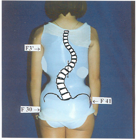
The objectives of the thoracic section are to correct the coronal plane curve, derotate the thoracic vertebral column and obtain a more normal physiological sagittal configuration, (Chêneau, 1996a, 1996b; Chêneau et al., 1997). The trimlines in the thoracic section, which are l ocated on the posterior superior aspect of the brace, have an asymmetrical shape. Pressure zone 1 is applied two vertebras above and two vertebras below the apex on the c onvex side of the thoracic or thoracolumbar curve. Its shape in the transversal plane is oblique and is applied in the dorsal lateral aspect of the patient's back. The function of this pressure is for the correction of the thoracic or thoracolumbar curve in the coronal plane and rotation of the vertebral column in the transverse plane (figure 3.17).
The objectives of the thoracic section are to correct the coronal plane curve, derotate the thoracic vertebral column and obtain a more normal physiological sagittal configuration, (Chêneau, 1996a, 1996b; Chêneau et al., 1997). The trimlines in the thoracic section, which are l ocated on the posterior superior aspect of the brace, have an asymmetrical shape. Pressure zone 1 is applied two vertebras above and two vertebras below the apex on the c onvex side of the thoracic or thoracolumbar curve. Its shape in the transversal plane is oblique and is applied in the dorsal lateral aspect of the patient's back. The function of this pressure is for the correction of the thoracic or thoracolumbar curve in the coronal plane and rotation of the vertebral column in the transverse plane (figure 3.17).
,
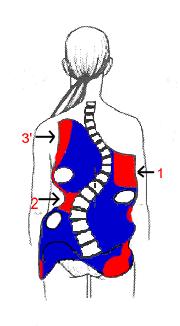
Figure 3.17 Posterior view of a patient wearing the Chêneau brace.
Pressure zone 1 (represented as in the figure as 1) is applied on the convex side of the thoracic curve in the coronal plane. This force works with the two counterforces in pressure zones 3 and 2 on the opposite side (represented in the figure as 3 and 2), which corrects the curve by a 3-point pressure system. Reference from Master by thesis on the Cheneau brace Grant I. Wood, 2003.
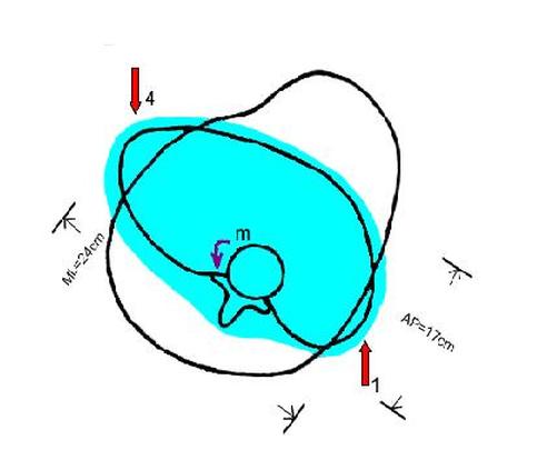
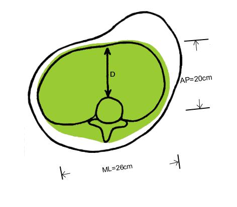
The derotation and sagittal plane normalisation is obtained through a pressure coupling mechanism, which clamps the larger diameter of the thorax, (figure 3.18).
a
|
b
|
Figures 3.18a and b Transverse view at the thoracic level of a right thoracic curve. The figures show detorsion of the trunk and spine (represented in blue for figure a and green for figure b) in the Chêneau brace. 1 and 4 in the figures represent pressure zones 1 and 4. ML and AP in the figures represent the oblique medial lateral length and the oblique anterior posterior width respectively of the thorax. M represents the turning moment. D is the distance between the ventral aspect of the body of the vertebral column. Reference from Master by thesis on the Cheneau brace Grant I. Wood, 2003.
a) Pressure zone 1 that is located on the convex side of the coronal plane curve, produces an oblique force. This force works with pressure zone 4 on ventral side to produce M, which derotates the trunk and the spine.
b) These pressures reduce the ML (from 24cm in figure a to 21cm in figure b) of the thorax and produce an increase of the AP (from 17cm in figure a to 20cm in figure b) of the thorax. This derotates the thoracic region and moves the trunk and spine backwards. As a result, this increases the length of “D” the sagittal diameter of the thorax.
Pressure zones 1 and 4 reduce the larger diameter of the thorax and increase the smaller diameter. These actions reduce the humps and fill-in the flat areas. This dorsal displacement of the spine, fills in the dorsal expansion zone 5 (figure 3.19), as a result, this reduces the thoracic hypokyphosis. The dorsal thorax is not in contact with the brace, however, the space is important for respiratory movement, and permits small voluntary and involuntary movements as well as the patient's growth. This provides an active mechanism of correction in the direction of derotation and rekyphosis.
,
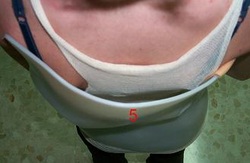
Figure 3.19 Dorsal superior view of the thoracic section of a patient wearing a Chêneau brace.
The dorsal expansion zone 5 (represented in the figure as 5) in the thoracic region allows the spine to move dorsally when the patient breathes. This results in a double mechanism of correction from a flat back to concavity and derotation. Patient in above Cheneau brace hand modified and delivered in Malaga Spain by Grant Wood, reference from Master by thesis on the Cheneau brace Grant I. Wood, 2003.
The dorsal expansion zone 5 (represented in the figure as 5) in the thoracic region allows the spine to move dorsally when the patient breathes. This results in a double mechanism of correction from a flat back to concavity and derotation. Patient in above Cheneau brace hand modified and delivered in Malaga Spain by Grant Wood, reference from Master by thesis on the Cheneau brace Grant I. Wood, 2003.
A force is applied to the anterior hump in pressure zone 4 and this lifts the breast approximately 3cm. The breast, which is positioned lower than the contralateral one, is repositioned in support. The trimlines of the ventral cranial aspect of the brace are designed to lift the breast, without impinging on it. The contralateral breast is covered by expansion zone 7 of the brace. This expansion zone provides a space for the trunk and spine derotation. The location of the pressure zone 40 is on the ventral aspect of the brace and is adjacent to the pressure zone 1, which is on the convex side of the thoracic or thoracolumbar curve. The function of this force is to reduce the medial lateral distance of the thorax, this corrects the thoracic hypokyphosis in the sagittal plane by causing flexion of the thoracic vertebral column (figure 3.20).
Pressure zones 3 and 3’ are applied to the shoulder that is in retropulsion or the contralateral shoulder to the convexity of the coronal plane thoracic curve. The retropulsion shoulder is deviated dorsally, laterally and inferiorly therefore pressure zones 3 and 3’ are applied to the shoulder to push it ventrally, medially and superiorly. The trimline in this axilla is approximately 3cm above the axilla´s original position. Its shape in the sagittal plane tilts towards the midline of the body and turns slightly inward. The contralateral axilla is left free, and its height and shape depends on the thoracic curve in the coronal plane. Also, these pressures reduce the visibility of the hump and the protruding shoulder blade as well as contributes to the derotation of the shoulders.
Pressure zones 3 and 3’ are applied to the shoulder that is in retropulsion or the contralateral shoulder to the convexity of the coronal plane thoracic curve. The retropulsion shoulder is deviated dorsally, laterally and inferiorly therefore pressure zones 3 and 3’ are applied to the shoulder to push it ventrally, medially and superiorly. The trimline in this axilla is approximately 3cm above the axilla´s original position. Its shape in the sagittal plane tilts towards the midline of the body and turns slightly inward. The contralateral axilla is left free, and its height and shape depends on the thoracic curve in the coronal plane. Also, these pressures reduce the visibility of the hump and the protruding shoulder blade as well as contributes to the derotation of the shoulders.
|
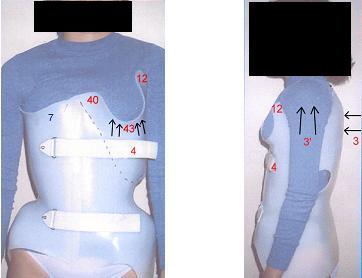
Figure 3.20
a) left image- The ventral aspect of the Chêneau brace on a subject with a right thoracic and left lumbar coronal plane curves. Pressure zone 43 applies slight pressure to lift the lower positioned breast to be on-level with the contralateral breast. Expansion zone 7 covers the breast without applying pressure or discomfort to it. Pressure zone 40 facilitates correction of thoracic hypokyphosis. b) right image-The pressure zones 3 and 3’ correct the shoulder tilt by moving the lower shoulder (left shoulder in this case) cranially and medially to reposition the lower shoulder to the same level or higher of that of the contralateral shoulder. Pressure zone 12 controls the shoulder ventrally. Patient in this Cheneau brace hand modified and delivered in Malaga Spain by Dr. Rigo, reference from Master by thesis on the Cheneau brace Grant I. Wood, 2003. |
|
LUMBAR SECTION
The lumbar section consists of pressure zones 2 and 1´ , which are applied one vertebra above and one vertebra below the apex of the lumbar curve. These dorsally located pressures are a continuation from the ventral pressure zone 4. Pressure zone 1´ extends almost to the posterior midline when lumbar hypolordosis is present and thus, it is needed to influence normal lumbar lordosis. In the case that it is not required to increase the lordosis, pressure zone 1´ is not utilised, and the pressure zone 2 extends less to the midline. The shape of these pressures are smooth and sufficiently deep enough to apply a corrective force to the lumbar curve.
The function pressure zone 2 is for the lumbar curve correction in the coronal plane. The 3-point pressure system is made up of pressure zone 2 and the counterforces from pressure zones 1 and 41. Pressure zone 2 is applied above and below the apex of the curve, pressure zone 1 is a counterforce which is applied to the opposite side of the lumbar curve and is located cephalically to the apex. Pressure zone 41 is also applied to the opposite side of the lumbar curve and is located caudally to the apex, which is below the iliac crest, as shown in figure 3.21.
|
Figure 3.21 The lumbar curve is corrected by the 3-point pressure system, which consists of pressure zones 2, 1 and 41. These forces are represented in the figure as 2, 1, and 41 respectively. Reference from Master by thesis on the Cheneau brace Grant I. Wood, 2003. |
PELVIC SECTION
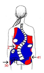
The pelvic section is designed to correct pelvic tilt and pelvic torsion. The pelvic tilt presents as a protrusion of the pelvis. Usually, the hemipelvis is higher on the thoracic convex side. The pelvic tilt is corrected by a 3-point pressure system that consists of pressure zones 41, 2 and 30 and expansion zone 16. The location of pressure zone 41 is on the iliac fossa, which is on the high side of the pelvic tilt. Pressure zone 2 is on the opposite side to pressure zone 41 and is located approximately 3cm above the iliac crest. Pressure zone 30 is on the opposite side to pressure zone 41, and is located on the greater trochanter. Expansion zone 16 has a window and is required on the low side of the hemipelvis. This provides a space for the hemipelvis to move into during correction.
Pressure zone 41 has a concave shape, which mimics the anatomical dimple-shape of the iliac fossa. Its inferior lateral trimline is at the caudal aspect of the iliac fossa. The pressure zone 30 is shaped so as to apply slight pressure on the greater trochanter, without causing discomfort. The trimline extends to the greater trochanter so that the counterforce works with pressure zone 2. Pressure zone 2 is shaped as previously mentioned in the lumbar section. The pelvic grip of the brace is designed so that it is higher on the side in which the pelvis is tilted lower, hence it has an asymmetrical shape.
The functions of these forces are to work together as a 3-point pressure system. Pressure zone 41 pushes the contralateral hemipelvis upward and the expansion zone 16 provides a space for the hemipelvis to move into for correction, (figure 3.22).
|
Figure 3.22 Posterior view of a right thoracic and left lumbar curves in the coronal plane. Pressure zones 41, 2, 30 and expansion zone 16 are represented in the figure as 41, 2, 30 and 16 respectively. The upward moment is represented as M. The thoracic convexity is to the right, therefore the pelvis tilt is to the left side. Pressure zone 41 pushes the pelvis between the two counterforces 2 and 30, therefore M is produced. This moves the left hemipelvis upward into expansion zone 16, as a result the pelvis is levelled. Reference from Master by thesis on the Cheneau brace Grant I. Wood, 2003. |
|
Pelvic torsion consists of iliac rotation and pelvis transversal rotation. The iliac rotation refers to a position of relative anteversion of the concave side of the lumbar curve and retroversion of the convex side of the lumbar curve. Anteversion is an abnormal position of the hemipelvis that is rotated and torsioned anteriorly therefore the ASIS is more prominent than usual, (figure 3.23). The contralateral hemipelvis would be in retroversion. Retroversion is an abnormal position of the hemipelvis, which is rotated and torsioned posteriorly therefore the ASIS is less prominent than usual, (figure 3.24). The contralateral hemipelvis would be in anteversion.
Rigo and Chêneau (1997, 2000) reported that this could be the consequence of passive tension of the lumbar fascicles of the erector spinae (longisimus thoracis and iliocostalis). Rigo (1999a) found that sometimes, combined or substituting iliac rotation causes a true three-dimensional iliac torsion (a bone deformity). Iliac rotation is corrected by pressure zones 37 and 34 as well as expansion zones 36 and 6 on the hemipelvis that is in anteversion. Pressure zones 38 and 2 as well as expansion zones 35 and 33 are applied to the hemipelvis that is in retroversion. Also by correction of the lumbar curve, the pelvis automatically assumes an anteversion position and therefore corrects itself.
The hemipelvis that is in retroversion, has its ventral inferior trimline of the brace that extends inferiorly to above the symphysis pubis to apply pressure zone 38. This is much lower than the contralateral side because pressure is required by pressure zone 38 for the correction of retroversion. The dorsal inferior trimline, for the same hemipelvis, is higher than the contralateral side because expansion is required by expansion zone 33 for the correction of retroversion. These inferior ventral and dorsal trimlines are asymmetrical and depend on the position of the pelvis.
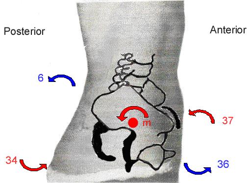
Figure 3.23 Sagittal plane view of the pelvis in anteversion. Pressure zones 37 and 34 as well as expansion zones 36 and 6 are represented in the figure as 37, 34, 36 and 6 respectively. The derotation moment is m. Forces 37 and 34 are applied above ventrally and below dorsally respectively to the centre of rotation. Expansion zones 36 and 6 are located below ventrally and above dorsally respectively to the centre of rotation.
Reference from Master by thesis on the Cheneau brace Grant I. Wood, 2003. |
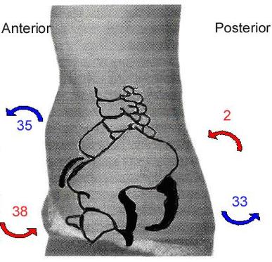
Figure 3.24 Sagittal plane view of the pelvis in retroversion. Pressure zones 38 and 2 as well as expansion zones 35 and 33 are represented in the figure as 38, 2, 35 and 33 respectively. Forces 38 and 2 are applied below ventrally and above dorsally respectively to the centre of rotation. A counter clockwise derotation moment is produced Expansion zones 35 and 33 are located above ventrally and below dorsally respectively to the centre of rotation.
Reference from Master by thesis on the Cheneau brace Grant I. Wood, 2003. |
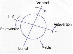
Figure 3.25
When the aforementioned deformity of the pelvis is due to an intrapelvic bone deformity from torsion and it is not from a compensated transversal rotation or coupled iliac rotation, it is very difficult and questionable if correction is possible by asymmetrical pressures on the pelvis, (Rigo, 1999b).
The pelvis is always transversally rotated to the opposite direction of the lumbar curve. Therefore, a left lumbar curve presents pelvis transversal rotation to the right (clockwise rotation) and a right lumbar curve presents pelvis transversal rotation to the left (counter clockwise rotation), as shown in figure 3.25. When pelvis transversal rotation is present, correction is required by balancing the positive cast, as described in the methods section.
The pelvis is always transversally rotated to the opposite direction of the lumbar curve. Therefore, a left lumbar curve presents pelvis transversal rotation to the right (clockwise rotation) and a right lumbar curve presents pelvis transversal rotation to the left (counter clockwise rotation), as shown in figure 3.25. When pelvis transversal rotation is present, correction is required by balancing the positive cast, as described in the methods section.
,
TRANSVERSAL DEFORMITIES
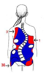
When the shoulders are deviated laterally from the hips, it is necessary to align the midpoint of the occiput over the sacrum in the same vertical plane as the shoulders are relative to the hips (Chêneau 1990, 1996a, 1996b). Pressure zone 41 works with pressure zones 3´ and 30 to balance the body via the 3-point pressure system (figure 3.26).
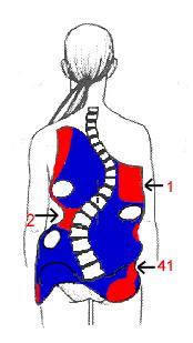
Figure 3.26 Posterior view of the forces required to correct a transversal deformity. Pressure zones 1, 30 and 3´ are represented in the figure as 1, 30 and 3´. Pressure zone 1 works with pressure zones 3´ and 30 to balance the body via the 3-point pressure system. Reference from Master by thesis on the Cheneau brace Grant I. Wood, 2003.
When the shoulders are deviated laterally from the hips, it is necessary to align the midpoint of the occiput over the sacrum in the same vertical plane as the shoulders are relative to the hips (Chêneau 1990, 1996a, 1996b). Pressure zone 41 works with pressure zones 3´ and 30 to balance the body via the 3-point pressure system (figure 3.26).
Figure 3.26 Posterior view of the forces required to correct a transversal deformity. Pressure zones 1, 30 and 3´ are represented in the figure as 1, 30 and 3´. Pressure zone 1 works with pressure zones 3´ and 30 to balance the body via the 3-point pressure system. Reference from Master by thesis on the Cheneau brace Grant I. Wood, 2003.
|
THIS WEBSITE IS
 |
Copyright BracingScoliosis.com 2008. All rights reserved. These are opinions only and viewers are at their own risk when acting upon the opinions therein. No part of the contents of this website or photos, videos images therein may be transmitted, copied or reproduced by any way without the written permission. |
